To illustrate this, we’ll use one of the shapes from Jesse James Garrett’s Visual Vocabulary–the continuation node–which can appear in either the horizontal or the vertical state.
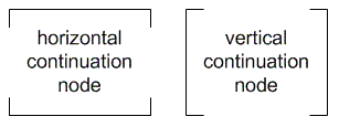
Although the Visio stencil for the Visual Vocabulary includes a shape for each state, it can be clumsy to switch from one to the other as you rearrange your site maps or flows. Employing a continuation node that toggles means literally flipping a switch to go from one state to another when you’re moving shapes around on your sitemap.
The basic idea
| The difference between combined shapes and grouped shapes A shape with multiple geometries is different from a group of shapes. Each shape in a group maintains a unique identity and has its own set of properties. When you change the formatting of a group of shapes, you are really assigning the new property to each shape en masse. You can also still change the properties of individual shapes within the group. |
Any shape in Visio is composed of one or more “geometries.” Each geometry represents a different component of the shape. Most shapes have just one geometry, but some have two or more. If you followed the Visio tutorial in the Special Deliverable #11, you’ll recall that to create the annotation shape, we combined a circle and the corner of a square. Each of these is a separate geometry.
When shapes are combined they become one shape, sharing all properties. In a combined shape, Visio can still distinguish between the different parts of the shape. We will take advantage of this feature to create a toggle-able shape.
A toggle-able shape has multiple geometries, each of which can be turned on or off depending on the state of the toggle. Our continuation node will have geometries representing the horizontal format and the vertical format. The toggle will turn off the horizontal geometries when the vertical ones are turned on, and vice-versa.
There are therefore three main steps to creating a toggle-able shape:
- Create all the possible states of the shape and combine into a single shape
- Add the toggle to the shape as an item in the context menu and define its behavior
- Adjust the visibility of the geometries based on toggle state
Step 1. Create all the possible states of the shape and combine into a single shape
The continuation node will end up with four geometries: two for the horizontal brackets and two for the vertical brackets. When you create the four brackets, make sure that each of them is a continuous line by clicking and dragging each leg starting on the end point of the previous leg. Arrange the brackets as they will appear in the final shape.
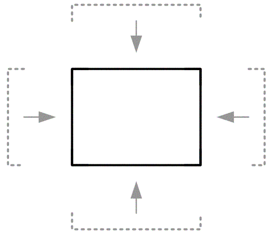
Because the horizontals overlap with the verticals, they will appear to be a single rectangle. Now, select all four brackets and choose Combine from the Shape > Operations menu. When you now select the shape, it will appear as if it is a single rectangle, and that all the brackets have been lost. Fear not, the geometries are still hidden in the shape.
Step 2: Add the toggle to the shape as an item in the context menu and define its behavior
There are two parts to this step and both occur in the ShapeSheet. Besides adding the menu item, we will need a place to store the current state of the shape. Since the state is binary (one of two possible values) we will use a Boolean (true-false) variable to store this information. In the next step we associate each value with a different state.
- Show the ShapeSheet by selecting the shape and then choosing Show ShapeSheet from the Window menu. Notice that the ShapeSheet has four Geometry sections. (Recall that a section in a ShapeSheet represents a different aspect of the shape.) In the next step we will learn how to distinguish which section corresponds to which bracket.
- For the toggle, the ShapeSheet needs two additional sections. Right-click anywhere on the gray area of the ShapeSheet and choose Insert Section… from the context menu. From the dialog box, put checks next to “User-defined cells” and “Actions.” Click OK.
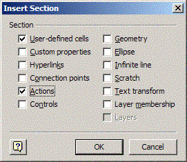
- The User-Defined Cells section is a place where we can store information about the shape that does not appear by default. This is where we’ll store information about the state of the shape. First, give the variable a friendly name by clicking on the red “User.Row_1” label and typing “state.” We can now refer to this variable from functions with “User.state.”

- Give User.state its initial value by entering TRUE into the Value column.

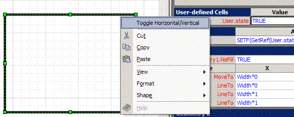
- The Actions section is what allows us to add items to the shape’s context menu. There are two critical cells: Action and Menu. Action specifies the function to execute when the menu item is chosen. Menu specifies the language to appear in the context menu. For Menu, enter “Toggle Horizontal/Vertical” or some equally dry indication of the purpose.

- It is in the Action column where the magic happens. In this cell, we’ll use a function that swaps the current value of User.state with the opposite value. Type the following into the Action cell:

The SETF() function sets the formula of the cell specified in the first argument. The GETREF() function allows us to refer to the cell itself, and not its value. Using GETREF() is required as the first argument in SETF(). The second argument of SETF() defines what the new formula should be–in this case, the opposite of what it is right now.
You can try it out now. Keep the ShapeSheet open, right-click on the shape and choose “Toggle Horizontal/Vertical” from the context menu. You’ll see the value in User.state change from TRUE to FALSE. Do this until it no longer amuses you.
| Entering formulas into ShapeSheet cells The sections of the ShapeSheet resemble Excel spreadsheets and can be a little finicky about having data entered into them. Once you’ve entered a formula or value, be sure to hit TAB or RETURN, or use the arrow keys to move to another cell. Clicking to another cell will not work. When you click on a cell when another one is active, Visio enters a cell reference into the active cell. This can be confusing and annoying. |
Step 3: Adjust the visibility of the geometries based on toggle state
Now we’ll move onto the Geometry sections of the ShapeSheet and modify the property that controls the visibility of the bracket. The visibility will be a function of our new User.state variable.
- Each Geometry section represents a different bracket, but Visio does not help us distinguish them. To ascertain which Geometry section refers to which bracket, you need to click on one of the cells in numbered rows of the section. These rows describe the shape using a series of directional commands (like “MoveTo” and “LineTo”.) Click on the first cell of the first numbered row of the section Geometry 1. In the drawing, you’ll see a small square appear on the shape. This shows you what part of the shape this row describes.
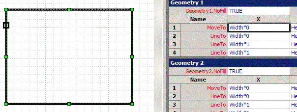
Hit the down arrow key and move through the rows of the Geometry 1 section. The square on the drawing will move around. As it does, you should be able to discern which bracket is being described. You may want to make a little reference for yourself.
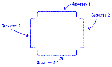
- Once you have established which section represents which bracket, you need to put the following formulas into the Geometry.NoShow cells. Make sure that you use the same formula for both the horizontal brackets and the OPPOSITE formula for the vertical brackets. In this example, assume Geometry sections 2 and 3 represent the horizontal brackets and Geometry sections 1 and 4 represent the vertical brackets. For Geometry2.NoShow and Geometry3.NoShow use:
User.state
For Geometry1.NoShow and Geometry4.NoShow use:
NOT(User.state)
As you enter these formulas you’ll see one set of the brackets disappear, depending on the setting of User.state. Now when you choose “Toggle Horizontal/Vertical” in the shape context menu, the brackets will switch orientation.
By creating an improved version of Jesse’s continuation node, you’ve had an opportunity to explore Visio’s ShapeSheets and formulas. You also used the following techniques:
- Combining shapes to create a new shape with shared properties
- Inserting sections into a ShapeSheet
- Creating a user-defined variable for storing additional shape data
- Adding a command to the context menu
- Using formulas for changing the value of a user-defined variable
- Modifying the NoShow property of a shape’s geometry
With these techniques you can create other toggle-able shapes (What about a checkbox that can be checked? Or a folder icon that can appear in both the opened and closed state?) and you can use these techniques to create shapes with other behaviors.
![]()

I’m embarassed to as this . . . how do I create brackets? I tried to using the draw tool, but that created 8 Geometries instead of 4, couldn’t tell what was what.
Oh, if someone can point me i the right direction, I can be reached at paddock@gmail.com.
Thanks for the tutorial Dan! At first I wondered while the shape wasn’t available for download, but when completing the tutorial took 5 minutes I realized why.
But the most valuable part of Visio shapes are the “connection points” that keep all the “arrows” connected to the “boxes,” and following the tutorial steps removes them.
Using the Visio stencil downloadable from jjg.net, I followed the tutorial but then added back in the connection points through the contextual menu “Insert Section > Connection points”.
The values that appear to work for the “continuation” shape are:
TOP Width*0.5 Height*1 0 in -1 in
BOTTOM Width*0.5 Height*0 0 in 1 in
LEFT Width*0 Height*0.5 1 in 0 in
RIGHT Width*1 Height*0.5 -1 in 0 in
Great stuff Dan.
I’ve also posted a couple “Stupid Visio Tricks” to my blog. Check ’em out at:
http://www.greenonions.com/index.php/index.php?cat=9
This series is proving most useful Dan, thank you. I took this idea a small step further in order to use the User-defined Cell value to set various properties with an IF statement.
For example:
This statement will toggle the fill from solid to transparent
FillPattern – IF(User.IsSolid,1,0)
and this one will toggle the line colour from blue to grey
LineColor – IF(User.IsSolid,RGB(187,189,203),RGB(0,22,74))
This works perfectly for the properties of a combined shape but the limitation I quickly bumped into is that I can’t use the same User-defined Cell value across shapes in a group. I presume that there is a syntax that will allow this but I have been unable to figure it out. Any thoughts?
This page from the Visio reference at Microsoft.com is quite useful for understanding shape references:
http://tinyurl.com/3qcyb